|
Overview
In order to test the structure's behavior under aerodynamic load, we
adopted the tried-and-true method of a "poor boy's wind tunnel."
The idea is to lash the item under test to the front of a vehicle and
then drive down a road in order to create relative wind for the test.
May 27, 2003
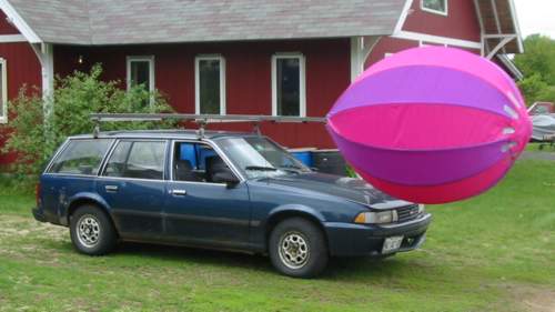
We made a series of high speed runs to test the structural integrity of a
model with 8 foot ribs. The model performed better than we could have hoped.
There was a bit of "scalloping" of the fabric and the the arc of the nose
flattened slightly (both of these deformations were expected.)
But overall, the structure withstood the aerodynamic loads beautifully.
The this model uses a "teardrop" shape (rounder in the front and more pointed
in the back than the longitudinally symmetric "football" shape used in earlier models.)
The runs were made at speeds up to 55 miles per hour using a model
with ribs that were 8 feet long and 1/8th of an inch in diameter (just a bit thicker
than a piece of spaghetti.) Even with such tiny ribs we were not
able to safely obtain speeds fast enough to get the model to collapse.
You can click
here
for a short movie (about 2 megabytes) of a run being made at 45 miles
per hour (the faster runs went by so quickly that image is largely
a blur.)
Here is what the rig looked like when it was standing still.
(actual runs were made with the
model cantilevered about 4 feet further in front of the front bumper.)
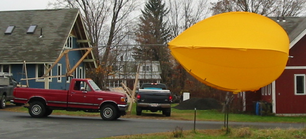
November 6, 2003
We made some initial runs of a larger model: 24 foot ribs - 18 feet overall length.
The curvature of the ribs in this model is the same as for the model above.
The differences are: 1) the number of ribs is reduced from 12 to 6 and 2) the
length of the ribs is increased by a factor of 3. The ribs in this model
are 0.312 inch diameter hollow carbon fiber tubes.
It is important to note that the ribs on this 1/5 scale model 'structurally to scale'
with our planned full-sized craft. In other words, the full sized craft will
be 5 times larger, but the ribs on the full sized craft will be 8 times the
diameter (2.63 inches.) If our scaling analysis proves correct,
then this model and the full sized craft should be able to sustain the same
aerodynamic forces (For more information on our scaling analysis,
see this
conference paper.)
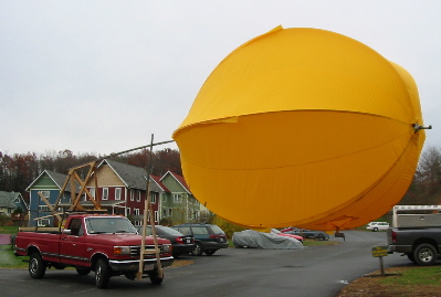
In order to provide sufficient clearances, we used a pickup truck rather
than a station wagon as the support vehicle.
For the purpose of testing, the
model is attached to a beam that runs along the central axis of the envelope
(the support beam can be seen extending past the nose.) This beam replaces
the central tensioning line while holding nose of the ship into the wind.
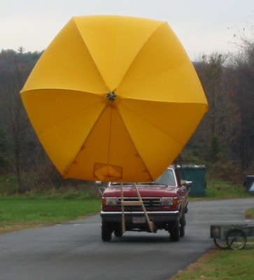
Clearly this configuration does not give complete information about the
envelope's ability to handle pitching moments on the nose. However, we are
most interested in determining the airspeed at which the nose of the ship
collapses. Therefore, the nose of the ship is attached to a slide mechanism
such that the beam can apply only tensile force to the nose. Therefore,
the beam provides no longitudinal support to the nose -- only lateral support.
|